480 Motor Wiring Diagram With Start And Stop

Typical Connection Diagrams Three Phase Motors Y Start Delta

54537d1340990049 How Reconnect Motor 480 Volts Back Original 230

3 Phase 240v Motor Wiring Diagram Electrical Diagram Diagram
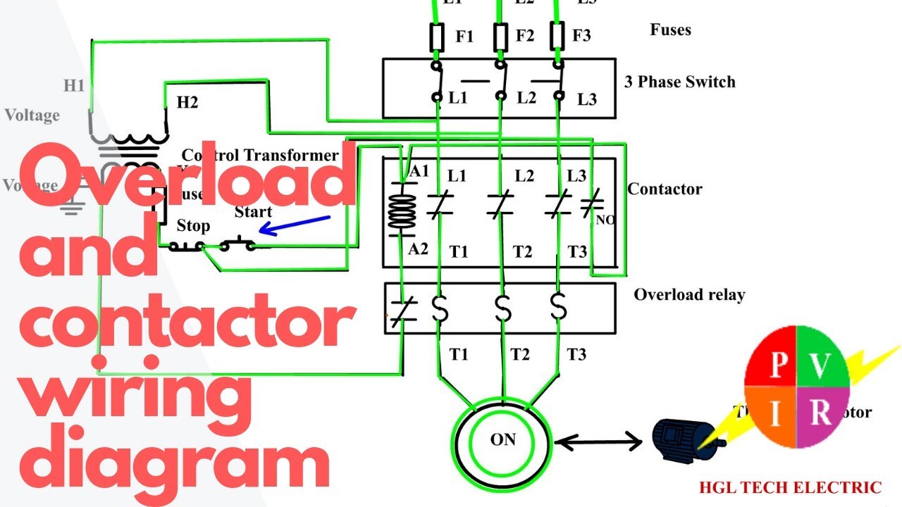
How To Wire A Contactor And Overload Start Stop 3 Phase Motor

New Wiring Diagram Three Phase Generator Diagram Diagramsample

Ac Motor Control Circuit Electronic Engineering Electrical
Osbourn in 480 welcome to our website we try to bring you relevant images to what you are looking for about 480 motor wiring diagram with start and stop.
480 motor wiring diagram with start and stop. 480 motor wiring diagram with start and stop posted by carrie j. With the switch closed the control circuit acts as a normal stop start station controlling a load connected to the pilot device power is sitting on the start and seal in terminals of the pushbutton. How to wire a contactor and overload. Whenever we need to start and stop the motor from more than one point then we may expand it through push buttons in the motor control circuit for example you may use this alternative power control wiring diagram of controlling a three phase motor from mo re than two places.
Control wiring 3 wire control start stop circuit the most common use of 3 wire control is a start stop control. Start stop 3 phase motor control wiring diagrams. See image below for an example of 3 wire control being used to pull in a contactor to start a 3 phase motor. Starting a three phase motor.
Start stop 3 wire control. Basic electrical components to wire a start stop station. Wiring diagram for a starter controlling a 480v motor with 120v start stop button of course the coil voltage must be and the motor can be whatever voltage this with a plc output straight to a starter and get rid of the start stop switch.

Motor Control Circuit Wiring Instrumentation Tools

Three Wire Control Circuit With Indicator Lamp

Headlight Relay Wiring Diagram In 2020 With Images Relay

09132211861 مهندس محمدیان تعمیر اینورتر اینورتور اینور تور درایو

Submersible Pump Control Box Wiring Diagram For 3 Wire Single

Electrical Wiring Diagram Symbols Electrical Wiring Diagram

Control Wiring 3 Wire Control Start Stop Circuit

Tractor Ignition Switch Wiring Diagram See How Simple It

Forward Reverse Three Phase Motor Wiring Diagram Non Stop

Renault Trafic Wiring Diagram Pdf On Images Free Download Amazing

Pin By Apple Liu On Three Phase Electric Motor Electric Motor

Running A Three Phase 480 Volt Motor On Single Phase 120 Volt

How To Wire 3 Phase Home Electrical Wiring
