Advance Ballast Wiring Diagram Resistor

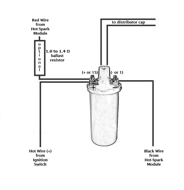
Ignition Coil Distributor Wiring Diagram

Ey 3029 Hid Philips Advance Ballast Wiring Diagram Wiring Diagram

Ballast Wiring Diagram Kgv Breitewiese De
Basic 12 Ballast Wiring Diagram Diagram Base Website Wiring
Igniter And Ballast Wiring With Painless Ih8mud Forum

Leanburn Conversion Or Thrash Those Points

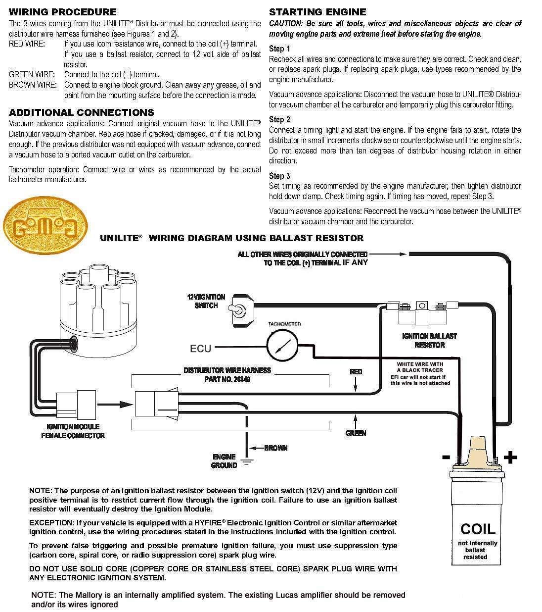
29349 ignition ballast.
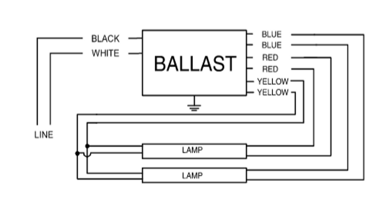
Advance ballast wiring diagram resistor. Variety of 2 lamp t8 ballast wiring diagram. Each component should be set and linked to other parts in specific manner. A wiring diagram is a streamlined standard pictorial representation of an electric circuit. Philips advance ballast wiring diagram.
Subscribe subscribed unsubscribe 87 9k. Setting up the ballast wiring part 1 duration. Parallel ballasts can only be wired in parallel according to the diagram on the ballast. How the ballast resistor works howstuffinmycarworks.
A resistor will be represented with a series of squiggles representing the constraint of current circulation. Mh ballast wiring diagram 100w mh ballast wiring diagram 150w mh ballast wiring diagram 400w mh ballast wiring diagram every electrical structure consists of various different pieces. Changing the wiring on a fluorescent light fixture from series to parallel involves changing the ballast from a series to a compatible parallel ballast. The great british car restoration 10 504 views.
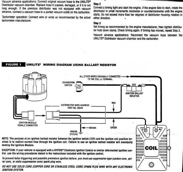
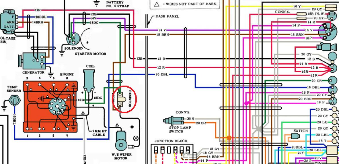
1969 plymouth fury 383. 2 lamp t12 ballast wiring diagram 4 lamp t12 ballast wiring diagram ge t12 ballast wiring diagram t12 ballast wiring diagram t12 ballast wiring diagram single pin t12 electronic ballast wiring diagram t12 fluorescent ballast wiring diagram t12 ho ballast wiring diagram t12 magnetic ballast wiring diagram t12 to t8 ballast wiring diagram. 2 lamp t8 ballast wiring diagram will definitely help you in increasing the efficiency of your work. Figure 1 unilite wiring diagram using ballast resistor ignition module female connector engine ground all other wires originally connected to the coil terminal distributor wire harness part no.
Philips advance ballast wiring diagram how to wire icn 4s54 90c 2ls g ballast advance ballast wiring diagram centium icn 4s54 90c 2ls g wiring diagram how to replace a t12. Philips advance ballast wiring diagram download. Reconnect the vacuum hose between the unilite distributor vacuum chamber and the carburetor. Led load resistor wiring diagram.
An antenna is a straight line with 3 small lines branching off at its end. It shows the components of the circuit as streamlined shapes as well as the power and also signal connections between the gadgets.
Rpi Engineering V8 Engines
How To Wire Up Ballast Resistor Corvetteforum Chevrolet
Https Encrypted Tbn0 Gstatic Com Images Q Tbn 3aand9gcrdhq Ddzer Gxzkw2eyvygdmulbcaz6a8tyvmlnrkp4jtj Bsp Usqp Cau
Wiriing Around Distributor Ignition Coil Ballast Resi Rolls
Engine Test Stand Wiring For A Bodies Only Mopar Forum
Wrg 4948 Battery Ballast Wiring Diagram
Bypassing Ballast Resistor Installing Pertronix Ignition For A
62 Ballast Resistor Purpose And Readings Corvetteforum
Mallory Unlite For A Rover V8

How To Bypass A Ballast 1000bulbs Com

Mallory Distributor Wiring Diagram In 2020 With Images Diagram
How Do I Wire My New Electronic Ignition 1978 Spider Alfa
Duraspark Ii Wiring Question Page 2 Ford Muscle Cars Tech Forum