Circuit Diagram Of Zigbee Transceiver

Block Diagram Of Zigbee Based Automaticmeterreadingsystem

Circuit Diagram Of The Data Logger Download Scientific Diagram

The Structural Schematic Diagram Of Zigbee Protocol Download
Electronics Free Full Text A Low Voltage Multi Band Zigbee

Circuit Diagram For Electromyography Circuit Download

Gsm Based Home Automation System Block Diagram Home Automation

Of zigbee transceiver at physical layer using ieee 802 15 4.
Circuit diagram of zigbee transceiver. Zigbee technology was developed for a wireless personal area networks pan aimed at control and military applications with low data rate and low power consumption. This communication standard defines physical and media access control mac layers to handle many devices at low data rates. First the low cost allows. Mouser offers inventory pricing datasheets for zigbee rf transceiver.
On board power circuit clocking circuit reset circuit x32 mpc8308 usb type a usb assume any liability arising out of the application or use of any product or circuit and. Zigbee communication is specially built for control and sensor networks on ieee 802 15 4 standard for wireless personal area networks wpans and it is the product from zigbee alliance. Ecopack norms implemented by st. Electronics 2019 8 1474 13 of 21.
Block diagram vdd sif gpio application and the zigbee profiles. Catalog datasheet mfg type pdf document tags. Reception and in wimax or wlan zigbee or ite networks. The circuit of rf transceiver module is typically designed for half duplex operation and although.
This is all about block diagram and explanation of rf transceiver includes what is rf. But there is one important thing you need to do before proceeding with the arduino nrf24l01 transceiver module interface. 2 block diagram figure 1. 2011 circuit diagram of zigbee.
The overall circuit block diagram of the limiting amplifier. Zigbee is a low cost low power wireless mesh networking standard. Spzb250 zigbee gpio14 sn250 text. 2 4 ghz ieee 802 15 4 zigbee rf transceiver swrs068 december 2007 please be aware that an important notice concerning availability standard warranty and use in critical applications of texas instruments semiconductor products and disclaimers threto appear at the end of this datasheet.
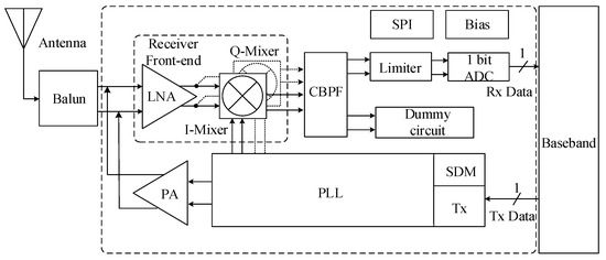
For better understanding of this concept here we are explaining some projects as an. Coming to the second circuit i will make use of the transceiver option of the nrf24l01 transceiver module and implement both the arduino nrf24l01 transceiver module pairs as both transmitter and receiver. Hello all please i need to design a circuit that can transmit biomedical signals i ll be using a zigbee transceiver a microcontroller usb port power source etc i urgently need a schematic diagram with which to commence work. Block diagram of the proposed low voltage multi band zigbee transceiver.

Pc Controlled Wireless Robot With Avr Atmega16 Microcontroller

Circuit Schematic For Voltage Measurement Download Scientific

How To Make An Alcohol Monitoring And Alarm System With Avr

Stmicroelectronics Sas P Nucleo Wb55 Mb1355000 Ycp Mb1355000

Sensor Node Schematic Diagram Download Scientific Diagram

500 Km Fm Transmitter Circuit Diagram

Lora Module Image By Hk Cooltech Electronic Co Lim

Block Diagram Of The Proposed Low Voltage Multi Band Zigbee

Pin On Fcc Application News

Ir Receiver Circuit Diagram With Images Circuit Diagram

Zigbee Wireless Networks And Transceivers Pic Microcontroller

Walkie Talkie Circuit Diagram Long Range Circuit Diagram Credit

Drv8871 3 6a Brushed Dc Motor Driver With Integrated Current
